Electronics studies
Analog circuit characterization
Built resistor, op-amp, diode, and filter circuits to investigate where measured behavior diverges from circuit models.
Individual laboratory studies · EEL3111C · May–July 2026
My contribution
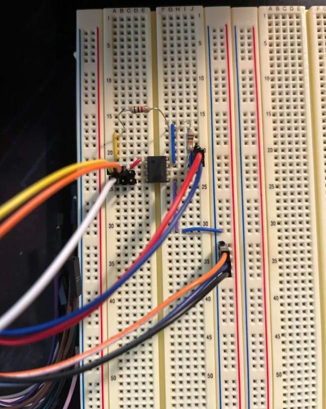
I modeled circuits in LTspice, assembled them on a breadboard, and measured their response in WaveForms. Across the labs, I compared predictions with observed gain, loading, and frequency response, then investigated the differences.
Results & observations
The measurements documented component-tolerance and loading effects, amplifier behavior, and differences between simulated and measured filter responses. The collection shows a repeatable approach to building, measuring, and troubleshooting analog circuits.
A model is only the starting point
These six studies follow the path from resistor-network simulation to measured active circuits. Lab 3 explored loading and resistor tolerances in LTspice. Lab 4 tested resistor ladders and two- and three-bit R–2R networks.
Op amps and filters
Lab 5 compared TLV272 simulation and bench measurements for offset, output swing, gain, and slew rate. Lab 9 compared passive and active RC filters using LTspice and the Analog Discovery network analyzer.
Conditioning signals and detecting thresholds
Lab 6 extended the op-amp work to buffering, DC level shifting, and differential-to-single-ended conversion, comparing LTspice predictions with oscilloscope measurements. Lab 8 tested half-wave and bridge rectifiers, capacitor-based peak detectors, and LM393 comparator circuits with LED indicators. Increasing peak-detector capacitance reduced ripple in the measured waveforms.
Finding the source of a mismatch
An incorrect capacitor shifted a filter cutoff, and incorrect resistor values changed the active low-pass response. Correcting components and checking power and measurement connections was part of getting meaningful results. The op-amp study also exposed a larger simulation-to-measurement discrepancy in slew rate.
Tools & methods
- LTspice
- WaveForms
- Breadboard prototyping
- Op-amp circuits
- Diode circuits
- Filter response
- Voltage measurement
- Circuit troubleshooting
- Tolerance analysis